Building the K-2 Pacific
This project was inspired by an Englishman who was infatuated with the Western Maryland. Back in the mid 1980's, the late David Lloyd published a series of articles about converting common N scale steam locomotives into WM steam. His articles appeared in Continental Modeler in Europe, and later in the WMRHS Magazine, the Blue Mountain Express. He had converted a Trix 2-10-0 into a WM flavored Decapod, and a Rivarossi 4-6-2 into a WM K-2 Pacific.
 Around this same time, I was working with my friend John Craft to design an N scale display layout for the WMRHS Museum in Union Bridge, Maryland. This was shortly after Mr. Lloyd's article ran in the BMX. I decided to write to him to see if he would be interested in building a K-2 for the museum layout. Several weeks passed, when a package arrived at my door. In it was his original model, along with a coach and a combine, plus a couple of other WM goodies. It turned out that at the time Mr. Lloyd was going through a messy divorce, and he needed to "divest" himself of his N scale collection. He had already sold the 2-10-0 to a friend, but he was happy to send the passenger set and a pair of FA-2's in Fireball paint as a donation to the historical society's collection.
And we were glad to have it! Despite it's antiquated drive with no flywheel and big old brass gears, the engine ran smoothly, and even quietly. During the 6 years I was active at Union Bridge, it logged dozens, if not hundreds of hours. In 2004, the Society began working on a new layout (the one I built was in the way of a needed library expansion) and they wanted to inventory and tune up the rolling stock while the transition took place. I volunteered to work on it, since I could do that without a lot of traveling, and I was pleased to see the old Pacific still in decent shape and ready to be put back in service.
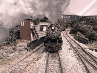
David Lloyd's original K-2 Conversion
The locomotive that David built had the appearance of the K-2's early in their career. This included the stock Rivarossi boiler tube pilot. He also left many of the stock details alone, although he did address the most visible detail, the location of the sand dome.
K-2 Step by Step
Click on the thumbnails for a larger view of the images.
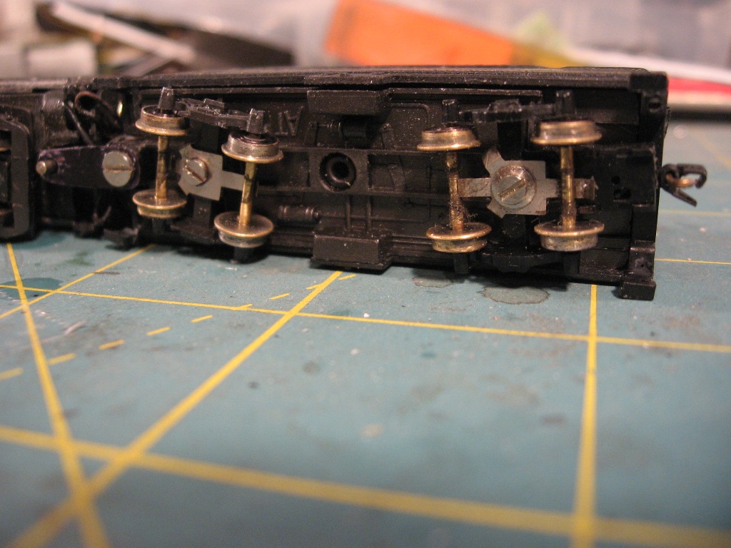
1.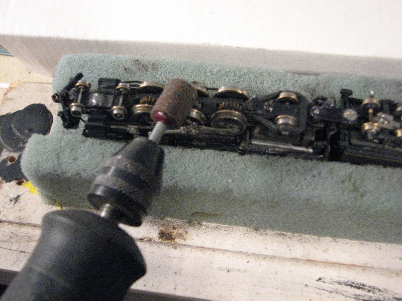 Turning Down the Flanges - I run on Atlas code 55 track, so this old "legacy" engine had the dreaded bumpty-bump on the tie problem due to it's 1970's era jumbo flanges. Something had to give. I did this before I installed the DCC decoder. First, I replaced the wheelsets on the tender with sets from an old Con Cor passenger car. They have the low profile flanges, and have a solid wheel on one side which provides for electrical contact in the tender. For the drivers, I placed the engine on its back in a foam cradle, and connected a power pack to the pilot truck and tender pick-ups. While the wheels turned, I used a Dremel Motor Tool with a grinding drum on it to carefully reduce the flange depth. You have to do this with a lot of patience, and be careful not to take off too much. Once I had enough ground down, I used a jeweler's file to round off the outer edge of the flange. This prevents the wheel from catching at switch points, and trying to climb over the rail on curves. The pilot and trailing trucks were a little trickier.
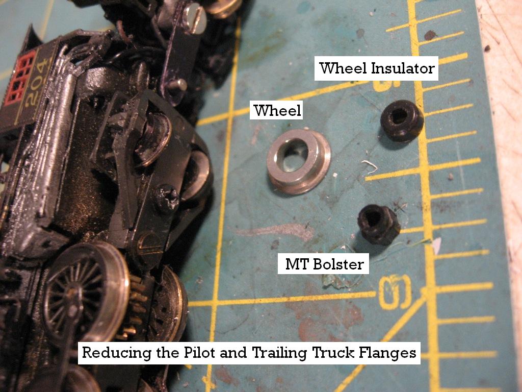

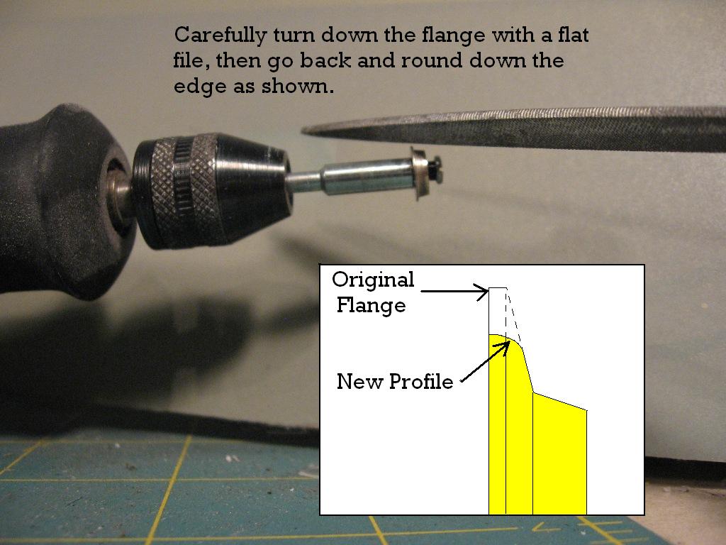
These wheels are not standard diameter, so I had to figure out how to work with them. The pilot truck worked out very easily. I pulled the wheels from the axle, and was able to chock one wheel at a time into a cutting wheel attachment from the Dremel. The Dremel served as a lathe, and I worked the flange down with a small file, again rounding off the edge. For the trailing truck, I used the same process, but the insulator at the axle was much bigger. So I pulled out the insulator, and used a Micro Trains bolster, which fit snuggly, and provided a good base to put in the cutting wheel chock.
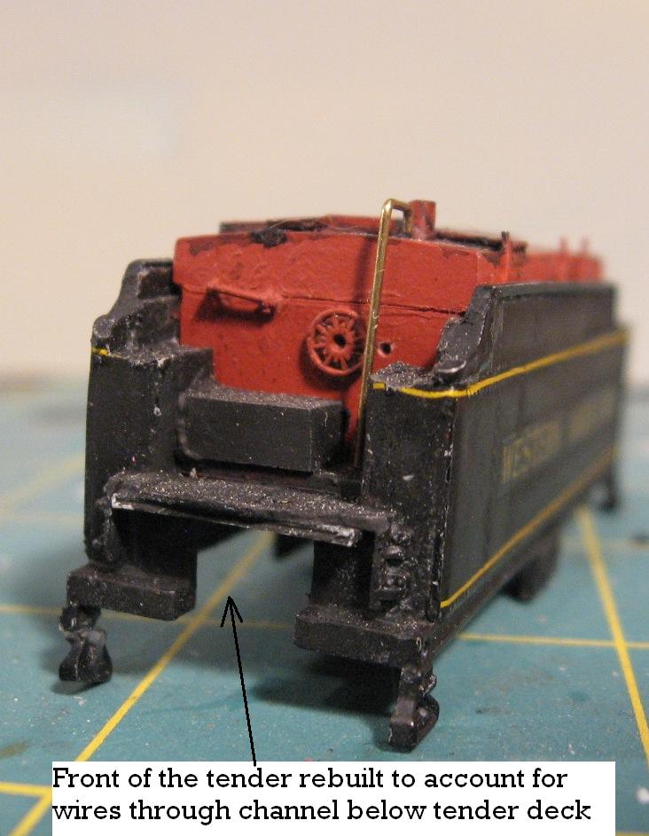
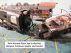
2. Shortening the Drawbar - Since I was going to install DCC, and I was pretty sure the decoder would end up in the tender, I knew I would have to change the drawbar. The factory drawbar makes the power connection between the tender pick ups and a post that connects directly to the motor. With DCC, such a connection would surely cause the magic smoke to escape, so it had to go. In its place, I cut a new styrene drawbar that shortens the distance between the engine and tender by almost 1/8", a big improvement. Instead of the solid electrical contact, I ran the five wires I needed to power the engine, lights and one side of the pick up under the walk plate at the front of the tender. I found that by twisting the wires by turning the tender over one time provides enough flexibility that it doesn't interfere with the operation of the engine.
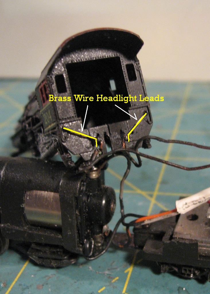
3.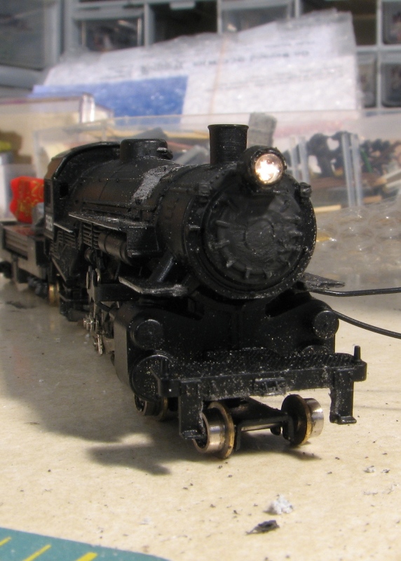 Moving the Headlight - Front view of the relocated headlight. I used a grain of rice bulb, 1.5 volts, which was much smaller than the headlight housing. I filled the gap in with gloss finish Mod Podge to create a full lens, which also has the effect of making the light appear brighter.
If I was a little brighter, I would have painted the inside of the housing silver, which would have added to the brightness... I also cut off the stock pilot to make it ready for a working coupler and a plow per WM practice.
4.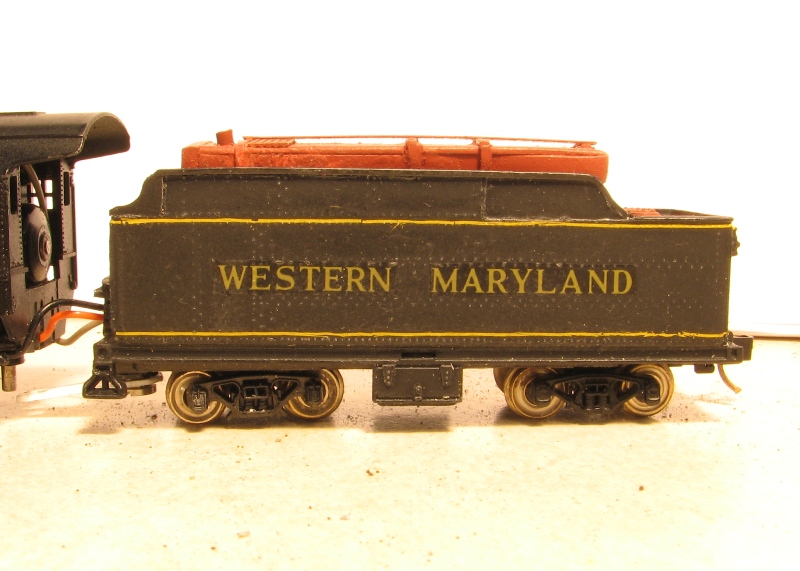 Modifying the Tender - Another key visual element of the Western Maryland Pacific is the longer flare at the top of the tender. I filed the rear flare square, then added a roughly 6' scale extension, and filed a new taper at the rear using a small jeweler's file. Comparing the model to the prototype photos, I was satisfied that I got the right look.
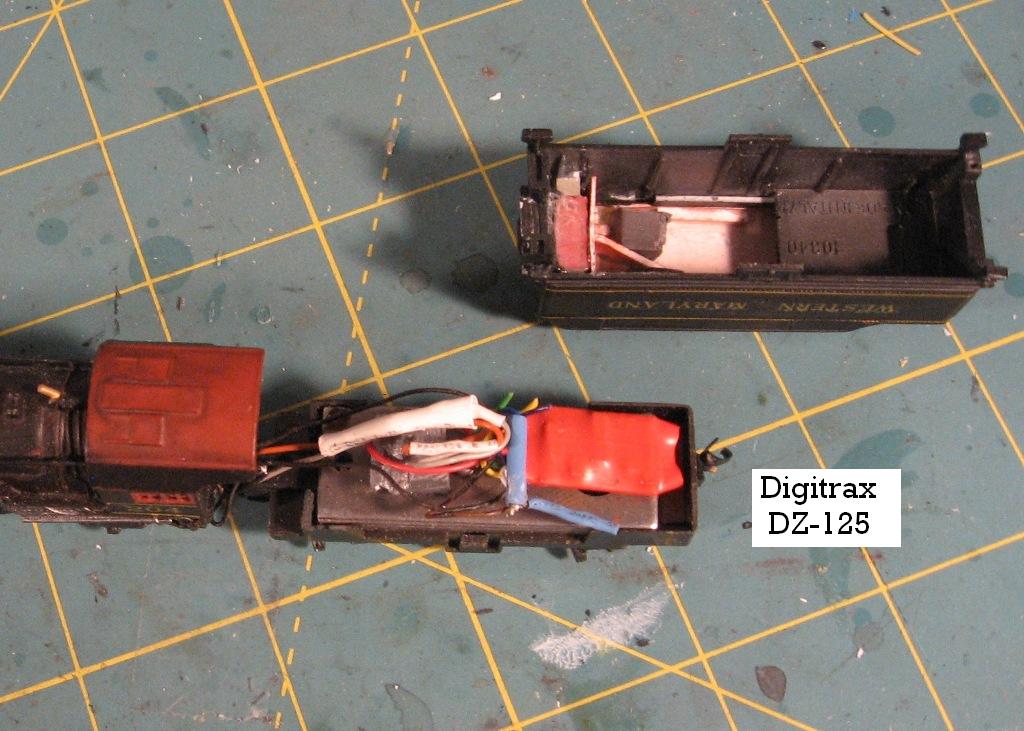
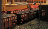
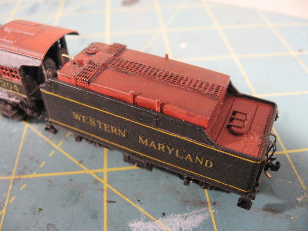
5. Building the Oil Bunker - The oil bunker is constructed of sheet and strip styrene, with a Gold Medal Models etched walkboard across the back, following prototype photos. I added the filler toward the front, along with a couple of brake wheels to represent valves. A piece of brass rod, left unpainted, represents the feed pipe that goes into the floor of the tender. In this shot you can see how I fed the decoder wires out from under the tender floor to make the necessary connections to the engine.
Building the K-2 Pacific
Modifying a Spectrum 2-8-0
Steam Era Freight Cars
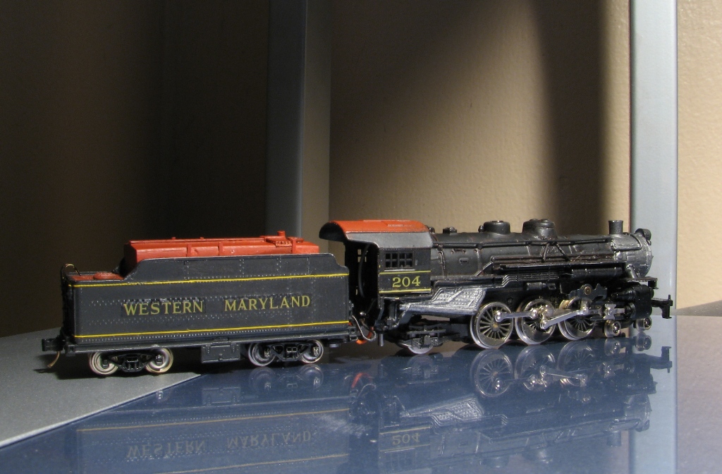
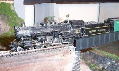
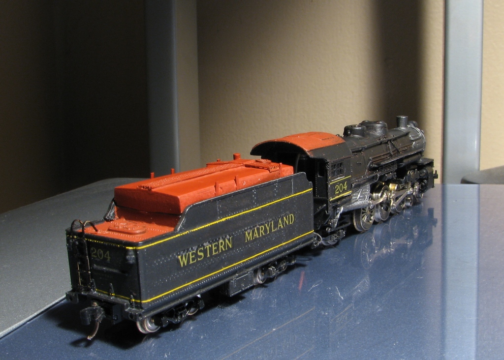
WM K-2 Pacific converted from an old Rivarossi 4-6-2.
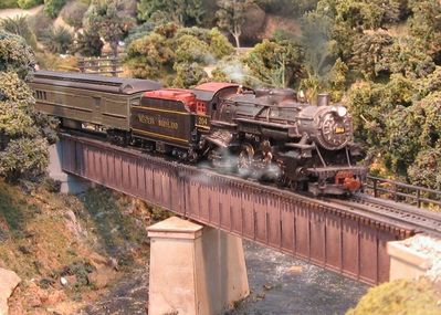
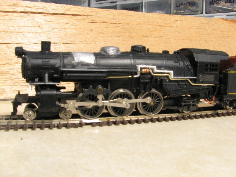
The Rivarossi shell resembles a basic USRA design, which has the sand dome toward the front, and the bell mounted at the top of the smoke box. The stock headlight is also located in the middle of the smokebox door, and he moved it up to where the bell had been. You can see the differences in the stock model shown below.
Stock Atlas/Rivarossi Pacific
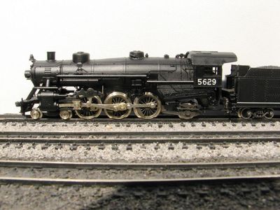
After I packed up the WMRHS equipment and took it back to Union Bridge, I decided that I needed to take on this project, with the added challenge of installing DCC in it. In August of 2008, I spotted a good deal on an old Atlas/Rivarossi Pacific on eBay, and the die was cast.
My goal was to build a more modern K-2, which would require a plow pilot. I also wanted to build my model to be one of the engines converted to burn oil so it could operate in Baltimore City, which had adopted a strict smoke ordinance. This would require a substantial rebuilding of the tender to add an oil bunker, as well as some rearrangement of appliances under the walk boards. Fortunately, the only surviving K-2, #202 now residing in Hagerstown Municipal Park, is an oil burner, so in addition to a fair number of available reference photos, I can go and have a closer look myself.
![]()
6.
Installing the Decoder - I looked at all the possibilities for locating the decoder, and as I suspected, inside the tender turned out to be the best choice. I wanted to have an operable headlight, as well as the motor leads, so that meant a minimum of four wires had to pass between the engine and tender. Since the old Rivarossi design only had tender pick up from one rail, I could install the red wire for the engineer's side to the pick up there, and run the black wire up to the front to pick up from the left rail.

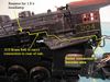

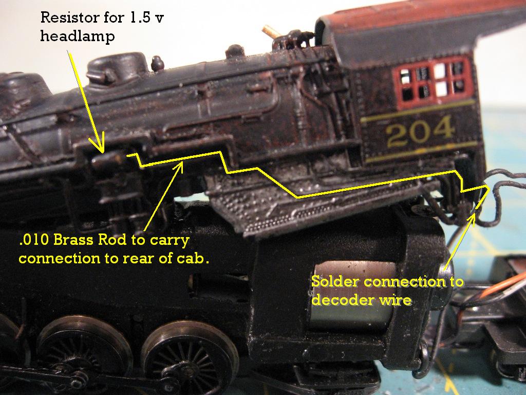
I also shortened the drawbar between the engine and tender to close up the distance between them, and also to help hide the bundle of 5 wires. At that point I made the necessary connections to power the motor, and get pick up from the left side of the engine. The diagram above also shows how I used brass rod on the outside of the boiler shell to power the headlight. I usually cut a trench in the weight inside the cab for the wires, but these old Rivarossis have that fragile Zanac alloy, I didn't want to cause it to break down.
7.
Modifying the Boiler, Adding Weight - I cut the USRA sand dome out, and squared up the opening. You can also see the back of the headlight here. The wire for the grain of rice bulb angles down into the top of the smokebox. To cover it up and prevent light leaks, I filled the area in with matte finish Mod Podge and let it dry. I used a chunk of lead from an old drain pipe to fill the hole. I also used some strip styrene to modify the walk boards. To get juice to the headlight, I needed to add a resistor. There isn't much room inside the shell, so I used some brass rod to make some piping, as well as carry the current. I put the resistor above the air pumps. I fashioned a new sand dome out of lead, and filed the top flat. The original sand dome was then filed flat on the bottom, and put on top of the lead to give it some detail. I used some brass rod with styrene spacers to add the hand rails down the top of the boiler, and bits of decoder wire to represent the sanding hoses coming down from the sand dome.
8.
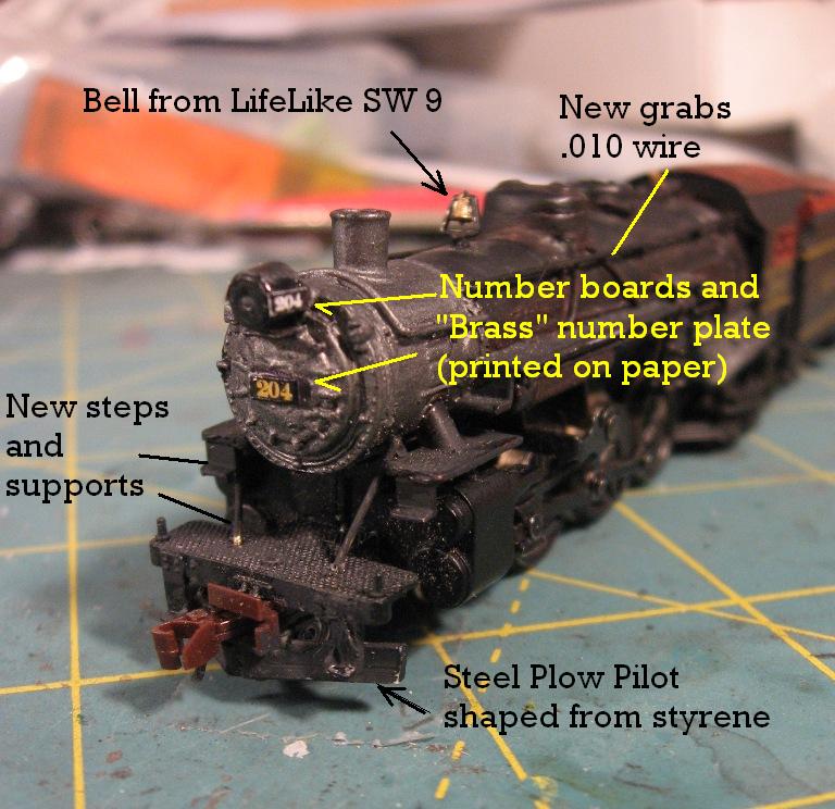
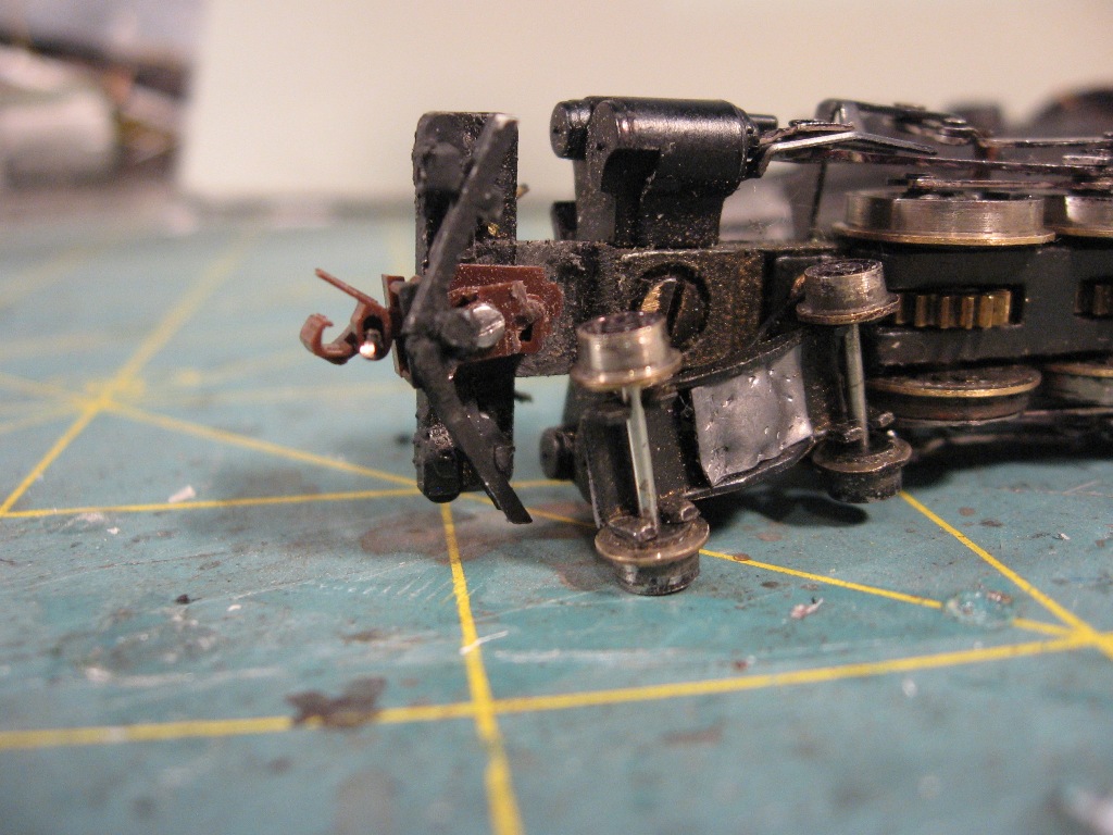
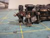
Rebuilding the Pilot and Adding Details - Around the time the oil bunker was added to 204, her original boiler tube pilot was replaced with a steel plow. I modeled this with some strip styrene that filed a concave profile into, and mounted it under the stock pilot floor. I had to carefully trim out the original pilot, and also made allowance for the installation of a Micro Trains coupler. You may want to use a Z-scale coupler, which would look more appropriate, and more easily clear the swing of the pilot truck. Here's a look at the underside of the installation. You'll note that I added a small square of self-adhesive sheet lead (gleaned from a ceiling fan balancing kit) to assist the tracking of the pilot truck.
9.
Paint and Lettering - I started with my favorite, the big rattle can of gloss black. This gave me a smooth surface for the lettering. The roof and tender top are sprayed with Oxide Red Primer, also from a can. I brushed on the graphite color for the smoke box, and a dull silver for the firebox. The lettering is from a Micro Scale set, which I set with Walther's Solva Set, then finished with a coat of Testor's Dullcote.
10. Lessons Learned - This project was full of unexpected challenges, as well as unexpected delights. While the design of the drive is definitely less than we accept today, it is a sturdy one, with thick brass gears and a large can motor. I understand that many have replaced their motors after years of service, and that replacements are readily available. If it comes to pass that I should need one, I would definitely take on the project. This was also the first steam engine I performed major surgery on (I've done a couple of nips and tucks, but nothing along this order) and I'm glad I did. Now I find myself eyeballing other steam models, and imagining how I might alter them to gain a more Western Maryland flavor. I've also gained valuable experience putting a decoder into an older mechanism, so this is now in my repertoire! I hope you've enjoyed this experiment in kitbashing as much I did accomplishing it.